Friday, May 30, 2014

Program for PIC 16F877A Microchip

v  Now, what we need to do is create a some coding on the  PIC by using MPLAB software. Actually there have many software’s can be used to create the program but we prefer this software because it’s straight to the point what we want to control the component, easy to manage the burning for Microchip PIC16F877A.


INFO: - This is the sample of  the software (MPLAB IDE v8.66)
Figure 2: Programing by used MPLAB software


v  I am using PIC16F877A microcontroller for my project and we did some exploring on the programming, what language to use, what IDE and also which is best suited for this PIC.
v  So I have decide to use assembly language instead of C language. The main reason is that the projet we been doing requires alot of programming lines and I’m just afraid that the flash memory of the microcontroller is small and cannot accomodate all the programming lines. For assembly language, it only require small flash memory when compared to C language. So we have decided to use assembly to program my project to save my flash memory space.
v  After doing research on a few software, namely MPLab, CCS compiler, Proteus, PICKit2, 8051 Dats and excreta. I realise that MPLab, CCS compiler is to write and compile C language. MPLab can be use to write and compile assembly language as well. Then we can use PICKit2 to burn the compiled program into the PIC microcontroller. I can’t use Daats because it can only write and compile Atmel microcontroller only.

    So, there we have it, we decided to use  MPLab together with PICKit2 for my project as it is the most suitable software for PIC microcontroller; to write, compile and burn my program.
Figure 3: Board installation after burning process

Figure 4: Testing procedure


SK40C Construction


Figure: Top view of board
v  After burn my program, we put in the PIC  at the SK40C board and solder for other component such as in figure above.
Figure: Bottom view of board
v  We used the Port C (RC1/T1OSI/CCP2) Pin 16 for the BUZZER,  Port B (RB0/INT) Pin 33 for the SWITCH SENSOR and lastly, also Port B (RB1) Pin 34 for the VIBRATE SENSOR. All of the Ground we combine it at the VSS Pin 12 and 31.

Tuesday, May 27, 2014

PICkit 2 PIC Programmer


The UIC00B PIC Programmer is design to program PIC microcontroller which includes most of the PIC family. In this project, the PIC Programmer is used to program the programming written using MikroC PRO for PIC inside the PIC16F877A as shown in Figure 1. This PIC Programmer comes together with the PICkit 2 Programmer, which will enable it to program the programming inside the PIC16F877A through this software as shown in Figure 2.

               This also allow user to quickly program and debug the source code while the target PIC is on the development board. Since USB port is commonly available and widely used on Laptop and Desktop PC, UIC00B is designed to be plug and play with USB connection. This programmer obtained its power directly from USB connection, thus NO external power supply is required, making it a truly portable programmer. This programmer is ideal for field and general usage. UIC00B offers reliable, high speed programming and free windows interface software.
Figure 1: USB ICSP PIC Programmer UIC00B

Figure 2: PICkit 2 Programmer Software

Saturday, May 24, 2014

MPLAB SIMULATION

MPLAB Integrated Development Environment (IDE) is a comprehensive editor, project manager and design desktop for application development of embedded designs using Microchip PICmicro and dsPIC microcontrollers. IT is product of Microchip Inc. and is an effort to make source code development as smooth and comprehensive as possible. It is called an Integrated Development Environment, or IDE, because it provides a single integrated “environment” to develop code for embedded microcontrollers.

            In the development of programming aspect, the MPLab are used to write down all the source code and coding for smart car instruction. Figure 1 shows how the MPLab software would appear on the desktop. All the source codes are written down into this software are would be built.
Figure 1: MPLab Software Editor

In addition, the source code will be built and the output of the successfully source code will appear through the window as shown in Figure 2. The successful output will create hex file (.hex) that needed to burn the programmer or instruction into pic microcontroller.

Figure 2: Output of Source Code

Monday, May 19, 2014

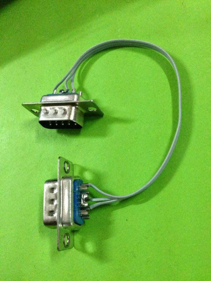
Female & male SUB – D 9 Serial Pin Connector

The DE-9 D-sub 9-pin connector is often mistakenly referred to as the "DB-9" connector.  The "E" refers to the shell size.  A "DB-25" connector has a "B" size shell, but the common nine-pin connector is smaller and has an "E" size shell.
            
This  connector (regardless what you call it) is used for a variety of purposes.  Two common applications are RS-232/EIA-232 (serial) connections (including UPS cables), and a variety of video interfaces on the IBM PC.  


Here's a good set of figures for D-sub 9 male and female connectors, as viewed from the pin side (not the solder side):

Refer at the Table 1, this is table of pins commanly used for RS-232 (Serial):
Table 1: RS-232 Serial Connection


Figure: Male SUB – D 9 pin connector and Serial cable.


Thursday, May 15, 2014

USB Burner

UIC00B offers low cost yet reliable and user friendly PIC USB programmer solutions for developer, hobbyist as well as students. It is designed to program popular Flash PIC MCU which includes most of the PIC family. Besides 8bit, it can also program 16bit and 32bit PIC MCU. On board ICSPTM (In Circuit Serial Programming) connector offers flexible methods to load program, UART Tool and Logic Tool. It supports on board programming which eliminate the frustration of plug-in and plug-out of PIC MCU. This also allows user to quickly program and debug the source code while the target PIC is on the development board. Since USB port is commonly available and widely used on Laptop and Desktop PC, UIC00B is designed to be plug and play with USB connection. This programmer obtained its power directly from USB connection, thus no external power supply is required, making it a truly portable programmer. This programmer is ideal for field and general usage. UIC00B offers reliable, high speed programming and free windows interface software.

Figure: USB Burner for PIC16F877A

Sunday, May 11, 2014

Piezo Buzzer

Piezo buzzer is an electronic device commonly used to produce sound. Light weight, simple construction and low price make it usable in various applications like car/truck reversing indicator, computers, call bells etc. Piezo buzzer is based on the inverse principle of piezo electricity discovered in 1880 by Jacques and Pierre Curie. It is the phenomena of generating electricity when mechanical pressure is applied to certain materials and the vice versa is also true. Such materials are called piezo electric materials. Piezo electric materials are either naturally available or manmade. Piezo ceramic is class of manmade material, which poses piezo electric effect and is widely used to make disc, the heart of piezo buzzer. When subjected to an alternating electric field they stretch or compress, in accordance with the frequency of the signal there by producing sound.


The above image shows a very commonly used piezo buzzer also called piezo transducer operating at DC voltage. Encapsulated in a cylindrical plastic coating, it has a hole on the top face for sound to propagate. A yellow metallic disc which plays an important role in the producing sound can be seen through the hole.

Piezo buzzers are small electronic devices that emit sounds when driven by low voltages and currents. They are also called piezoelectric buzzers. They usually have two electrodes and a diaphragm. The diaphragm is made from a metal plate and piezoelectric material such as a ceramic plate.


Operation
Piezo buzzers operate using the piezoelectric effect. A voltage that is applied to the leads causes the piezoelectric element to shrink or stretch. This makes the diaphragm vibrate as it bends, thereby producing sound waves. Piezo electric elements are made from crystals, such as quartz or Rochelle salts.


Sounds
The sounds emitted may be extremely low or ear-piercing. They may be made loud enough to cause hearing loss. These sounds include noises such as buzzing, chirping, ringing, sirens, and beeps.

Capacitor Electrolytic

Capacitors are components that are used to store an electrical charge and are used in timer circuits. In this project, the capacitor may be used to produce a timer and filter. Sometimes capacitors are used to smooth a current in a circuit as they can prevent false triggering of other components such as relays. When power is supplied to a circuit that includes a capacitor – the capacitor charge up. When power is turned off the capacitor discharges its electrical charge slowly.


A capacitor is a little like a battery. Although they work in completely different ways, capacitors and batteries both store electrical energy. A battery has two terminals. Inside the battery, chemical reactions produce electrons on one terminal and absorb electrons on the other terminal. A capacitor is much simpler than a battery, as it can't produce new electrons - it only stores them. Inside the capacitor, the terminals connect to two metal plates separated by a non-conducting substance, or dielectric. We can easily make a capacitor from two pieces of aluminum foil and a piece of paper. The dielectric can be any non-conductive substance. However, for practical applications, specific materials are used that best suit the capacitor's function. Mica, ceramic, cellulose, porcelain, Mylar, Teflon and even air are some of the non-conductive materials used. The dielectric dictates what kind of capacitor it is and for what it is best suited. Depending on the size and type of dielectric, some capacitors are better for high frequency uses, while some are better for high voltage applications. Capacitors can be manufactured to serve any purpose, from the smallest plastic capacitor in your calculator, to an ultra capacitor that can power a commuter bus. NASA uses glass capacitors to help wake up the space shuttle's circuitry and help deploy space probes. Here are some of the various types of capacitors and how they are used.

•Air - Often used in radio tuning circuits

•Mylar - Most commonly used for timer circuits like clocks, alarms and counters

•Glass- Good for high voltage applications

•Ceramic - Used for high frequency purposes like antennas, X-ray and MRI
Machines


•Super capacitor – Powers electric and hybrid cars6

Thursday, May 8, 2014

TC35i Terminal

In this project, the TC35i terminal GSM modem is used as it was provided from the university. It operate under 12V and it voltage operate equal as the voltage provided as battery Motorcycle. Basically, the TC35i Terminal modem operate from the TC35 GSM Engine. It is a major functional component of the TC35 Terminal that handles all the processing for audio, signal and data within a GSM cellular device. Internal software runs the application interface and the whole GSM protocol stack. AUSART forms the interface to the Terminal Circuit. Figure 36 show the front view picture of  TC35iT. From the picture, we can see the RS232 connector that will be connected to PIC interface circuit.
Figure: TC35i Terminal

Tuesday, May 6, 2014

Vibration Sensor

Vibration sensors are sensors for measuring, displaying, and analyzing linear velocity, displacement and proximity, or acceleration.
Purpose of vibration measurement is to detect the vibration however subtle and unnoticed by human senses is a telltale sign of machine condition. Abnormal vibration indicative of problems with an industrial machine can be detected early and repaired before the event of machine failure; because such a failure is potentially costly in terms of time, cost, and productivity, vibration measurement allows industrial plants to increase efficiency and save money. Therefore, vibration analysis is used as a tool to determine equipment condition as well as the specific location and type of problems.


Switch

In electronics, switches are classified according to the arrangement of their contacts. A pair of contacts is said to be "closed" when current can flow from one to the other. When the contacts are separated by an insulating air gap, they are said to be "open", and no current can flow between them at normal voltages. The terms "make" for closure of contacts and "break" for opening of contacts are also widely used. A switch may be directly manipulated by a human as a control signal to a system, such as a computer keyboard button, or to control power flow in a circuit, such as a light switch. An ideal switch would have no voltage drop when closed, and would have no limits on voltage or current rating. It would have zero rise time and fall time during state changes, and would change state without "bouncing" between on and off positions.


Saturday, May 3, 2014

Block Diagram for Project

This project contains 3 sections which is the hand phone, the GSM modem and the PIC16F877 microcontroller with the alarm circuit. The hand phone will communicate to the GSM modem in 2 way communication using mobile phone platform. This is including giving an instruction from mobile phone or receives information from the GSM modem. The GSM modem not only communicates to the mobile phone but also communicate to the microcontroller in 2 way communication. The GSM modem will give the instruction to the PIC after encrypted the instruction receives from mobile phone. The instruction is encrypted in binary or hexadecimal notation that can be understood by the microcontroller. At the same time, the microcontroller will provide information to be send to the owner through the GSM modem.

            
      The PIC microcontroller will control the whole operation to the system. It used to gain control to the alarm circuit and also receive detection from the sensor such as vibration sensor. The operation in the microcontroller is more to comparison data because the microcontrollers only do the job when there are inputs given to it and compare to the program that burner to it. Figure show the connection to each section of the system.