Simply of our flow chart is start
is the start and through the alarm on, if Yes means active sensor and if No means
will go to Read SMS. When the sensor detects a vibration active or it will act
as the Yes On buzzer and will send SMS to the consumer, and when acting as a
No. Read SMS and will also go to Start again. Read SMS stands for what is
transmitted by the GSM modem when detecting vibration of PIC programming, and
when Yes means that a user will request or reply SMS from PIC programming, and
if No act to start again. Location Request is Yes will act to send a forward
location in the GSM modem to the user.
However, the block diagram of this
project can be summarized in Figure Block Diagram. Figure Block Diagram illustrates this connection
for mechanical components and how they relate to the control system. As shown
in figure below, component parts, such as vibration sensor, switching, buzzer was
connected to the PIC16F877A microcontroller. This also shows that vibation
sensor and proximity sensor analog stick on the controller board. The
microcontroller will control the actual condition of vehicles using vibration
sensor in response to the occurrence of the output such as buzzer. In other
words, PIC16F877A acts as the brain for the control of all connected components.
The MAX232 is an integrated circuit that converts signals from an RS-232
serial port to signals suitable for use in TTL compatible digital logic circuits.
The MAX232 is a dual driver/receiver and typically converts the RX, TX, CTS and
RTS signal.
The drivers provide
RS-232 voltage level outputs (approx. ± 7.5 V) from a single + 5 V supply via
on-chip charge pumps and external capacitors. This makes it useful for
implementing RS-232 in devices that otherwise do not need any voltages outside
the 0 V to + 5 V range, as power supply design does not need to be made more
complicated just for driving the RS-232 in this case.
The receivers reduce
RS-232 inputs (which may be as high as ± 25 V), to standard 5 V TTL levels.
These receivers have a typical threshold of 1.3 V, and a typical hysteresis of
0.5 V.
The later MAX232A is
backwards compatible with the original MAX232 but may operate at higher baud
rates and can use smaller external capacitors – 0.1 μF in place of the 1.0 μF
capacitors used with the original device.
It is helpful to
understand what occurs to the voltage levels. When a MAX232 IC receives a TTL
level to convert, it changes a TTL Logic 0 to between +3 and +15 V, and changes
TTL Logic 1 to between -3 to -15 V, and vice versa for converting from RS232 to
TTL. This can be confusing when you realize that the RS232 Data Transmission
voltages at a certain logic state are opposite from the RS232 Control Line
voltages at the same logic state. To clarify the matter, see the table below. For
more information see RS-232
Voltage Levels.
PIC16F887 has the same pin
diagram as PIC16F877A. Therefore, you can replace the PIC16F877A on your old
project with PIC16F887 without any problem. What is so special about this new
model of 8-bit PIC microcontroller? Let’s compare it side by side.
As the table shows, memory wise,
both 887A and 887 are the same, whereby both have 8K words of program memory
and 368 bytes of data memory. What attracted me to 887 is the internal crystal
that offers speed from 32KHz to 8MHz. This internal crystal can be tuned
through software register and it offers switchable operating frequency between
internal and external crystal during program runtime. With this option, we can
save the money needed for external crystal, avoid breakdown when the external
crystal stop working and you have two extra I/O pin that was initially used for
external crystal. The two extra pins are RA6 and RA7 which is bidirectional I/O
pin, great! If you compare with PIC16F877A pin diagram you will not get these
two pins.
What’s next? The ADC of course!
PIC16F887 has increased the analog input to 14 channels, and every pin can be
configured to analog or digital independently. As you might have notice, analog
input is getting more important because more sensors come with analog output as
it is the easiest method to deliver wide range of information by just single
wire interface. These sensors include infrared distance sensor, Ultrasonic
range finder, Accelerometer, Gyro, Gas sensor, LDR, and many more. With extra
analog input, you are able to integrate more analog sensor into your design.
Despite the increased number of analog input, there is another good feature in
this model for those who do not need the analog input. In a scenario where some
of you experience failure after you connect analog sensor to, let’s say, RA0
and RA5, digital input to RA2; and when you want to develop the program you
notice that to make RA0 and RA5 become analog input, RA2 will become analog
input too. Once the pin is analog, requesting digital logic will result in
wrong info.
However, you are still able to use it, provided that the program
changes the analog pin to digital pin every time before it reads digital input
pin, and same step apply when the program wants to read analog input pin. Isn’t
it troublesome? Many would agree with me. Worry no more with PIC16F887 as the
selection of analog input or digital input pin are truly independent of each
other. PIC16F887 uses ANSEL and ANSELH register to configure 14 channels of AN
pin to analog input or digital pin. ANSEL controls eight pins of PORTA+PORTE
while ANSELH controls six more pins at PORTB.
OK, what else can we get? If you
have noticed, there is one I/O pin left out from previous discussion. This pin
is RE3. PIC16F877A offers 33 I/O pin while PIF16F887 provides 36 I/O. We know
two extra I/O are from the crystal pins, where is another? It is actually the
MCLR pin which we normally use it for Reset purpose. For PIC16F887, user may
have the choice to tie MCLR internally to VDD and use pin 1 as RE3. However,
this pin can only be used as digital input.
I think that those facts
mentioned are sufficient for me to replace my PIC with this new model, but
there is another important factor for me to consider before migrating to it.
Everyone would agree with me, of course that is the price. PIC16F887 is much
cheaper than PIC16F877A. You should be able to get a PIC16F887 with only half
the price of PIC16F877A. This is the main factor, more features yet cheaper
price; with this, we definitely have no reason to resist it.
PIC
stands for Peripheral Interface Controllers (PIC). PIC microcontroller is a
family of Harvard architecture microcontrollers made by Microchip Technology.
PIC microcontroller which know as a single-chip microcomputer, well suited for control
and automation of machine and process in electronics and have more attractive
features that suitable for wide range applications. PIC is popular due to their
wide range ability, availability of low cost or free development tools and
serial programming capability.
PIC16F877A is a small integrated
circuit (IC) available with 40 pins package. This PIC is a powerful and very
easy-to-program CMOS FLASH-based 8-bit microcontroller packs introduced by
Microchip Technology.
The PIC16F877A features 256 bytes
of EEPROM data memory, self programming, an ICD, 2 Comparators, 8 channels of
10-bit Analog-to-Digital (A/D) converter, 2 capture/compare/PWM functions, the
synchronous serial port can be configured as either 3-wire Serial Peripheral
Interface (SPI™) or the 2 – wire interated Circuit (I²C™) bus and a Universal
Asynchronous Receiver Transmitter (USART). All of these features make it ideal
for more advanced level A/D applications in automotive, industrial, appliances
and consumer applications.
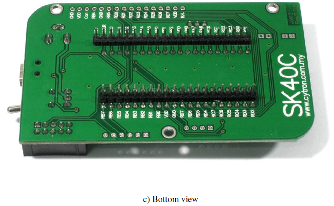
A – 2x5 box header for UIC00A/B, USB ICSP PIC Programmer.
B – JP10 port reserved for PICkit programmer. User may used PICkit 3 at this port to load program besides using UIC00B.
C – Reserved for UART communication. Tx and Rx pin of SK40C are connect to RC6 and RC7 respectively. Ensure PIC use have the correct UART pin (RC6 and RC7).
D – 2 LEDs (connected to RB6 and RB7) as active High output for PIC MCU. These LEDs are controllable from PIC MCU.
E – 40 pin IC socket for user to plug in any 40 pin PIC MCU (8 bit). It can either be 16F or 18F PIC. Of course the IC package should be PDIP. Please ensure the first pin is at the top side. Inside IC socket, there some electronics components, it include a 20MHz Crystal.
F – 2 x Push button connected to RB0 and RB1 of PIC MCU. This is extra input button for user. It can be programmed as input switch.
G – Push button with the function of Reset for PIC MCU.
H – 5K of trimmer to set LCD contrast.
I – JP9 is provided for USB. Connect this pin if users use USB port
J – JP8 is provided for LCD Backlight. LCD Display will have backlight if this pin is shorted.
K – Turn pin is provided for crystal. 20M Hz is default crystal provided in SK40C. However, the 20M Hz crystal can be removed and replace with other crystal. Just remove the crystal and put other crystal on turn pin without soldering.
L – Reserved for 2 x 16 LCD Display. User may solder 2x16 LCD display at this space if want to use it.
M – Consist of several line of header pin and turn pin. Header pin provide connector for user to solder SK40C to prototype board and use the I/O of PIC MCU. It is fully compatible between SK40B. Turn pin offer simple way to check voltage with multi-meter probe. 40 pins of PIC MCU except OSC (connected to crystal) are extended out to these pin. There is an extra pin on top of MCLR which is labeled as Vin, is connected to the input power.
N – DC power adaptor socket for user to plug in DC adaptor. The input voltage should be ranged from 7 to 15V.
O – USB connector for communication between devices and a host controller (usually personal computers). This function is only valid for certain model of PIC microcontroller. Please refer to USB interface section. The power LED will light ON when the USB cable is connected.
P – Power indicator LED for on board. It will light ON as long as the input power is correctly connected.
Q - Toggle switch to On/Off the power supply from DC adaptor.
Since
their introduction, MCUs have been used in almost every application that
requires certain amount of intelligence. The invention of microcontrollers has
its pros and cons. The main advantages of microcontrollers are given as
follows:
·Microcontrollers act as a microcomputer
without any digital parts.
·As the higher integration inside
microcontroller reduce cost and size of the system.
·Usage of microcontroller is simple, easy
for troubleshoot and system maintaining.
·Most of the pins are programmable by the
user for performing different functions.
·Easily interface additional RAM, ROM,
I/O ports.
·Low time required for performing
operations.
The
disadvantages for a microcontroller are:
·In contrast to microprocessors,
microcontrollers have more complex architecture.
·Only limited number of executions can be
performed simultaneously.
A microcontroller is a
small computer on a single integrated circuit containing a processor core,
memory, and programmable input or output peripherals. Neither program memory in
the form of NOR flash or OTP ROM is also often included on chip, as well as a
typically small amount of RAM. Microcontrollers are designed for embedded applications,
in contrast to the microprocessors used in personal computers or other general
purpose applications. Microcontrollers are used in automatically controlled
products and devices, such as automobile engine control systems, implantable
medical devices, remote controls, office, machines, appliances, power tools,
and toys. By reducing the size and cost compared to a design that uses a
separate microprocessor, memory, and input/output devices, microcontrollers
make it economical to digitally control even more devices and processes. Mixed
signal microcontrollers are common, integrating analog components needed to
control non-digital electronic systems. In this project the PIC16F877A are used
and Table 1 indicated devices features.
A Subscriber Identity
Module (SIM) card is a portable memory chip used mostly in cell phones that
operate on the Global System for Mobile Communications (GSM) network. These
cards hold the personal information of the account holder, including his or her
phone number, address book, text messages, and other data. When a user wants to
change phones, he or she can usually easily remove the card from one handset
and insert it into another. SIM cards are convenient and popular with many users,
and are a key part of developing cell phone technology.
Activating
a SIM Card
Since all of a user's
data is tied to the SIM card, only it needs to be activated when the person
opens an account with a cell phone service provider (also called a carrier).
Each card has a unique number printed on the microchip, which the carrier needs
to activate it. In most cases, the phone's owner can go either to the carrier's
website and enter this number in the appropriate tool or call the service
provider directly from another phone to get it turned on. SIM cards are tied to
a particular carrier and can only be used with a service plan from that
carrier.
Swapping
Handsets
One of the biggest
advantages of SIM cards is that they can easily be removed from one mobile phone
and used in any other compatible phone to make a call. This means that, if the
user wants to buy a new handset, he or she can activate it quickly by inserting
his or her old SIM card. The user's phone number and personal information is
carried on the card, so there's no need to do anything else to transfer this
information. Most phone applications (apps) are stored in the phone's memory or
secure digital (SD) card, however, so they will not be transferred to the new
handset.
Some cell phone
carriers lock their handsets; this means they will only work with SIM cards
from that carrier. This is especially common in the US, where service providers
sell the handsets at a discount in exchange for the consumer signing a
long-term contract for service. Handsets can be unlocked with the right code,
however, although the exact process varies by manufacturer and model. Any SIM
card can be used with an unlocked phone. Phones without a card, or with one
that is not compatible, can typically only be used for emergency calls.
Pre-Paid
SIMs
Pre-paid SIM cards are
also available, allowing a phone that's locked to the pre-paid carrier's
network or an unlocked phone to be used without a long-term contract. This type
of card is useful for people who don't want to be tied to one carrier, or who
want to try out a service provider before committing. It's especially useful
for international travelers, who can purchase a local SIM card to use their
phone abroad. This allows the user to keep the same phone - with the apps and
other settings that are stored in it - without paying international roaming
charges from the carrier back home. It also gives the traveler a local phone
number, making it less expensive for people to call the traveler from within
the same country.
SIM
Cards Sizes
SIM cards are made in
three different sizes to accommodate different devices. Most phones use
mini-SIM or micro-SIM cards, which are quite small - the mini is 25 mm by 15 mm
(0.98 in by 0.59), and the micro is 15 mm by 12 mm (0.59 in by 0.47 in). Full-sized
cards are much larger, 85.6 mm by 53.98 mm (3.37 in by 2.13 in), and are too
big for most phones. All cards are only 0.76 mm (0.03 in) thick, however, and
the microchip contacts are in the same arrangement. This means that, with the
proper adapter, the smaller cards can be used in devices designed for larger
ones.
Security
A SIM card offers
security for both the user's data and his or her calls. The cards can be
locked, meaning that only someone who has the correct personal identification
number (PIN) can use the card. If the phone is stolen, the thief cannot use a
locked SIM or get any information off of it without the PIN.
In addition, the card
has a secret authentication code and an encryption key that protect the phone's
transmissions. Although it is possible to "clone" a cell phone on the
GSM network and thus steal service, it's much more difficult than it is to
clone a phone on the competing Code Division Multiple Access (CDMA) network.
Because of the way the encryption information is transmitted to the carrier,
it's usually necessary to have physical access to the SIM card in order to copy
it.
Other Cell Phone
Technologies
Phones that operate on
the CDMA network do not use SIM cards; instead, most save the phone number and
other identifying information in the handset itself. While this can be less
convenient for users, CDMA is most common in the US, where handsets are usually
heavily subsidized and users may have less incentive to switch phones
frequently. In addition, some carriers, mostly in Asia, do use their own
removable card format, called a Re-Useable Identification Module (RUIM).
As technology changes,
however, more cell phone providers are upgrading to 3GPP Long Term Evolution
(LTE), which is based on GSM technology. This means that some sort of SIM card
is likely to be required for devices that use this network.
Short Message Service
(SMS) is a globally accepted service using GSM network and widely used in
mobile phones. It is a text messaging service component of phone, web, or
mobile communication systems. It is used the standardized communications
protocols that allow the exchange (sending and receiving) of short text
messages between fixed line or mobile phone devices. Short Message System (SMS)
messaging provides a convenient way to communicate between mobile phone devices.
The sending and receiving text message between mobile phones devices are
basically through Global System for Mobile Communications (GSM) network.
The use of SMS on
modern handsets was originated from radio telegraphy in radio memo pagers,
which used the standardized phone protocols and later defined as part of the
Global System for Mobile Communications (GSM) series of standards in 1985. As a
means, the process sending messages to and from GSM mobile handsets can be up
to 160 characters. Ever since then, support for the service has expanded to
include other mobile technologies such as ANSI CDMA networks and Digital AMPS,
as well as satellite and landline networks.
In addition to being a
great way of communicating people, SMS can be a useful way for applications to
exchange simple messages between devices. SMS works across most cellular
service providers, which does not require a direct connection between devices,
the infrastructure for the system is already in place.
Friend
Finder™ via SMS allows you to get location updates on your position or where
your friends are using the following methods:
Friend Finder™ Texts - Sends you an SMS
with a text description of your location or your friend's whereabouts upon
request.
Friend Finder™ Maps - Sends you an SMS
with a Google Map displaying your location or your friend's whereabouts upon
request.
Auto Friend Finder™ - Automatically
sends you from 5-16 SMS a day (depending on which Auto Friend Finder™ package
you're subscribed to) with text descriptions of your friend’s whereabouts.
Friend
Finder™ via WAP allows you to get location updates on your position or where
your friends are via:
Friend Finder™ WAP portal - Get text
descriptions or Google Maps displaying your location or your friend’s
whereabouts upon request
Use DiGi Friend
Finder™ to locate your friends and family without disturbing their activities.
Keeping abreast of your loved ones’ locations have never been this easy! You
can also use the service to pin-point your own location if you are lost.
IMPORTANT: You can only
use Friend Finder™ to locate those who have explicitly granted you the
permission to do so.
Friend
Finder™ is a revolutionary service by DiGi that allows you to use the phone
number of a friend or family member to find out where they are by tracking the
position of their mobile phones. You can also use Friend Finder™ if you get
lost to figure out where you are.All DiGi, Maxis and U-Mobile subscribers
(Prepaid and Postpaid) are eligible to use Friend Finder™.
There
are 3 types of charges associated with using Friend Finder™
Requests - These are charges incurred for every SMS message you send to 20000 that includes the keywords FF (e.g. FF FIND mobile number, FF OK, FF CANCEL>)
Data - These are charges incurred according to your 3G plan for using the Friend Finder™ WAP portal or DiGi Friend Finder™ application
Finds - These are charges incurred when Friend Finder™ manages to successfully locate you/your friend.
vSMS/WAP users:
§If the locations update you receive is in text form you will be charged 30sen/find.
§If the location update you receive includes a Google Map you will be charged 50sen/find plus data charges for viewing the map on the Friend Finder™ WAP portal.
vApp users:
§For each location update you receive, you will be charged 30sen/find plus data charges for using the DiGi Friend Finder™ application.
The
accuracy of the information provided by Friend Finder™ depends on the density
of cell towers around the mobile phone number you are tracking. The degree of
inaccuracy can vary from approximately 500 meters to a few kilometers.
If
you are using Friend Finder™ Texts, Friend Finder™ Maps or Friend Finder™ via
WAP, you can only use Friend Finder™ to look for one person at a time (i.e. you
can only list one mobile phone number is a Friend Finder™ request), but you can
make as many requests as you want in a day.
If
you are using Auto Friend™ Finder, you will receive location updates on
everyone you have assigned an Auto Friend Finder™ package to without having to
send Friend Finder™ a request via SMS or WAP to locate your friends.
You
can use Friend Finder™ to locate DiGi, Maxis or U-Mobile subscribers that have
given you permission to locate them as long as they are within the DiGi, Maxis
and/or U-Mobile network coverage area(s).