Saturday, June 7, 2014

Wednesday, June 4, 2014

THEORETICAL RESULT

Theoretically, the circuit will function when vibration occurs in cycles based on sensitivity sensors required, and when the sensor detects vibration it will turn the buzzer. At the same time the process of PIC16F877A Microcontroller and GSM modem will happen. The result of the process the user will receive a SMS "Alarm Warning", for starters Run Process program. Next, the user will reply to the SMS by typing "RST", which means that on last RESET buzzer. After the process, the tool will return the ALARM RESET, with the back like a normal circuit and the user simply type "LOC" for the location of the tool is that we put the bike in, and then the user will receive a SMS site processed by the GSM Modem. All these simple SMS programmed right into PIC16F877A Microcontroller and GSM Modem to produce result like the Figure 1.
Figure 1: Processing Result 

Video Demo FYP Project SSVT

http://www.youtube.com/watch?v=tE4ic6IZ8ao&feature=youtu.be

MAX232 Construction

Below, I have attached the components used for the MAX232 circuit construction. Click here for the MAX232 datasheet. For better understanding refer the comparison of MAX220 to MAX249 family here.


Figure 4: Ribbon cable connection between MAX232 interfacing and SK40C.
 (TX, RX) 


Monday, June 2, 2014

Configure the GSM Modem

Figure: TC35i GSM Modem with Siemens TC35i Module / RS232 GSM

INFO: - This is the sample of  the software (Hyper Terminal)
Figure 13: Configure Modem using AT Command


v  Using GSM modem provides information on Telco coverage in that area, if our vehicle close to the coverage or substations, GSM modem will close or accurate information, and if our vehicle away with telco it’s substation will provide the location of the area, Last of the address where the vehicle was, as we now Malaysia got wide coverage with branches Maxis, Celcom, DiGi, and so on.

v  In this project we use DiGi coverage to track the vehicle, because the coverage is quite broad Digi SIM card from another. How GSM modem to process the track itself which is the GSM modem, and after that she would forward the message received by the GSM modem to the left to consumer, it occurs after the user send a short message of “LOC” which was programmed in the PIC microcontroller.

v  In this hyper terminal, we make the configuration between GSM Modem and coverage of the Telco for better communication lines using AT Command.


Friday, May 30, 2014

Program for PIC 16F877A Microchip

v  Now, what we need to do is create a some coding on the  PIC by using MPLAB software. Actually there have many software’s can be used to create the program but we prefer this software because it’s straight to the point what we want to control the component, easy to manage the burning for Microchip PIC16F877A.
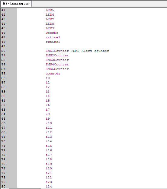
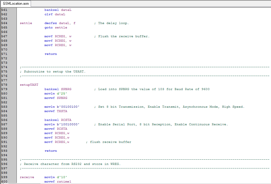
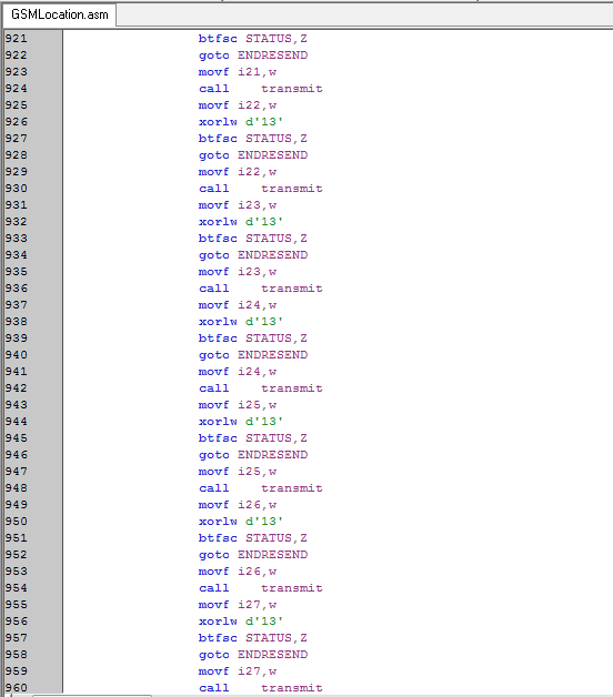
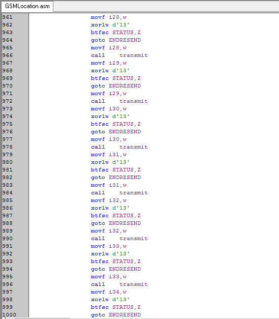


INFO: - 
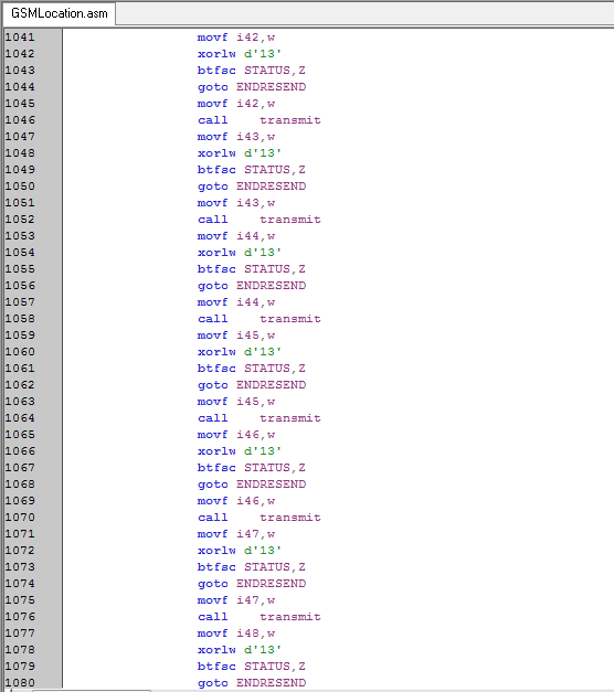
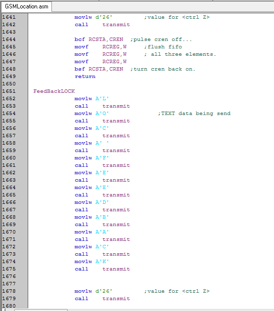
This is the sample of  the software (MPLAB IDE v8.66)
Figure 2: Programing by used MPLAB software


v  I am using PIC16F877A microcontroller for my project and we did some exploring on the programming, what language to use, what IDE and also which is best suited for this PIC.
v  So I have decide to use assembly language instead of C language. The main reason is that the projet we been doing requires alot of programming lines and I’m just afraid that the flash memory of the microcontroller is small and cannot accomodate all the programming lines. For assembly language, it only require small flash memory when compared to C language. So we have decided to use assembly to program my project to save my flash memory space.
v  After doing research on a few software, namely MPLab, CCS compiler, Proteus, PICKit2, 8051 Dats and excreta. I realise that MPLab, CCS compiler is to write and compile C language. MPLab can be use to write and compile assembly language as well. Then we can use PICKit2 to burn the compiled program into the PIC microcontroller. I can’t use Daats because it can only write and compile Atmel microcontroller only.

    So, there we have it, we decided to use  MPLab together with PICKit2 for my project as it is the most suitable software for PIC microcontroller; to write, compile and burn my program.
Figure 3: Board installation after burning process

Figure 4: Testing procedure